Test voltage table, real tester specifications and factory field notes — numbers taken directly from our technical documentation and nameplates, not rewritten from textbooks.
Yoanpower is the export brand of Wuhan Defu Electric (est. 1983), and our 0.1 Hz VLF high voltage generators are built to comply with the Chinese power industry standard DL/T 849.4-2004 (General technical requirements for ultra-low frequency high voltage generators). Everything on this page is copied from our own product manuals, factory test setup photos and nameplates. Where we don't have verified data, we say so instead of guessing.
Set the test voltage as Umax = 3 × U0, where U0 is the rated phase voltage of the cable (formula from our manual). All voltage values below are peak values, applied at 0.1 Hz, true sine wave. Acceptance (hand-over) test duration is 60 min; maintenance (preventive) test duration is 15 min — both copied verbatim from our manual. Voltage classes not listed in our factory table (11 / 15 / 24 kV) are struck through.
| System voltage | Cable U0/U (kV) | Acceptance test (hand-over) | Maintenance test (preventive) | Frequency | Value type | Standard basis |
|---|---|---|---|---|---|---|
| 6 kV | 3.6/6 or 6/6 | 3U0 = 11 / 18 kV peak 60 min | 3U0 = 11 / 18 kV peak 15 min | 0.1 Hz | Peak | Factory data sheet, citing DL/T 849.4-2004 and the Chinese industry standard “Test method of 0.1 Hz voltage withstand test for XLPE insulated power cables up to 35 kV”. Setting rule: Umax = 3U0. |
| 10 kV | 6/10 or 8.7/10 | 3U0 = 18 / 26 kV peak 60 min | 3U0 = 18 / 26 kV peak 15 min | 0.1 Hz | Peak | |
| 20 kV | 12/20 | 3U0 = 36 kV peak 60 min | 3U0 = 36 kV peak 15 min | 0.1 Hz | Peak | |
| 35 kV | 21/35 or 26/35 | 3U0 = 63 / 78 kV peak 60 min | 3U0 = 63 / 78 kV peak 15 min | 0.1 Hz | Peak | |
| Not in our factory table. By the manual's 3U0 rule with the IEC U0 = 6.35 kV, that works out to ≈19 kV peak — derived, not from the table; confirm with us before a hand-over test. | ||||||
| Not in our factory table. By 3U0 with U0 = 8.7 kV: ≈26 kV peak — derived; confirm with us. | ||||||
| Not covered by our documentation — uncertain. Send us your cable's U0 and we will confirm the setting. | ||||||
Frequency: 0.1 Hz is the standard test frequency. Our generators also output 0.05 / 0.02 / 0.01 Hz for high-capacitance test objects (see load table below).
Value type: peak (crest) values — our instruments display peak voltage and current, per the manual.
Standards basis: our factory documents reference DL/T 849.4-2004 (general technical requirements for 0.1 Hz VLF generators) and the Chinese industry standard “Test method of ultra-low frequency (0.1 Hz) voltage withstand test for XLPE insulated power cables up to 35 kV”. Levels from IEC 60502-2 / IEEE 400.2 are not listed in these documents — if your project is specified to IEEE 400.2, contact us and our engineers will convert the settings for you.
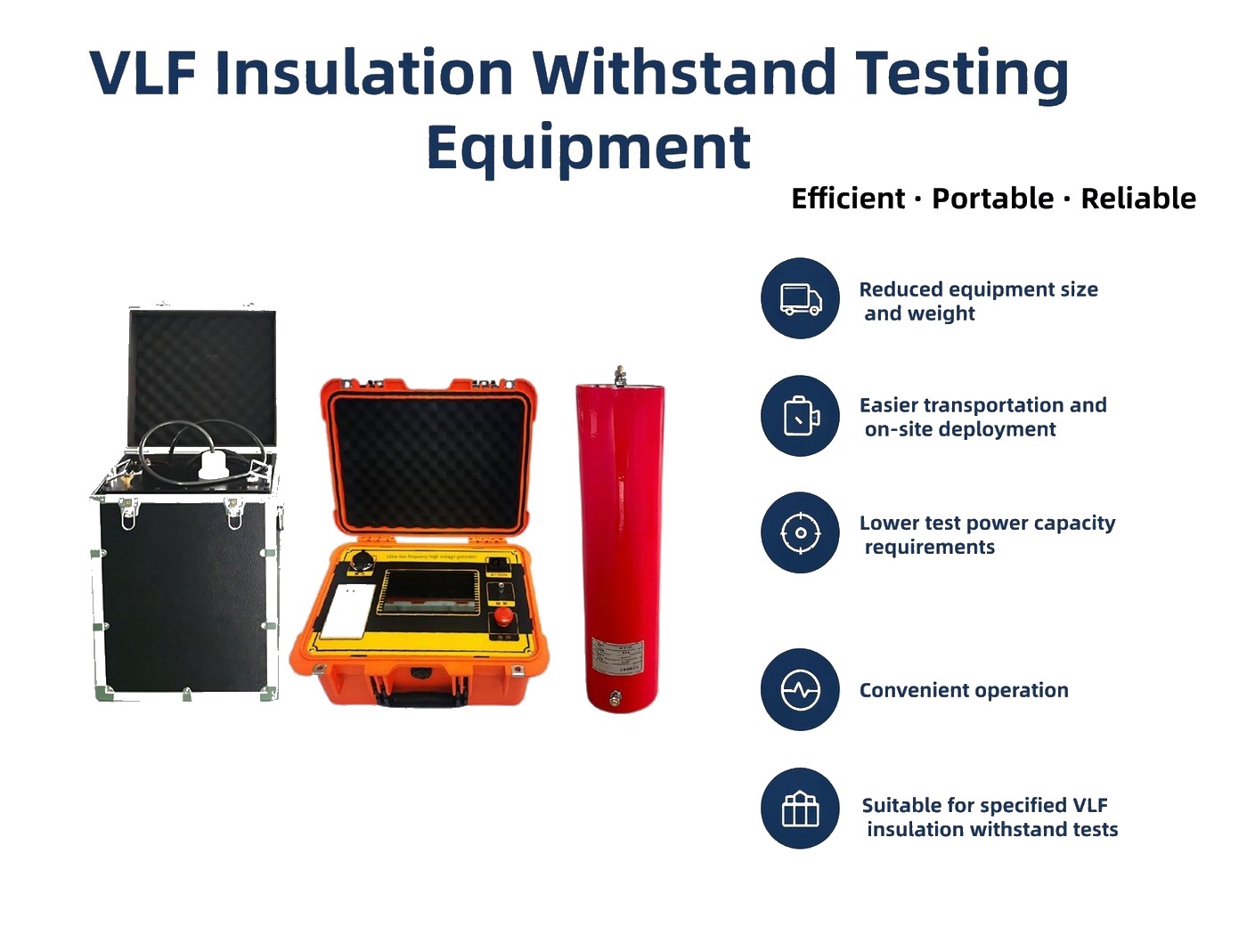
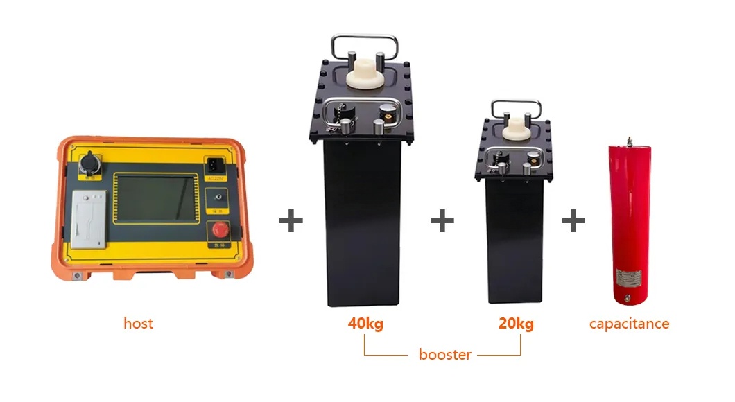
| Item | Specification (copied from manual / nameplate) |
|---|---|
| Rated output voltage | 30 / 40 / 50 / 60 / 80 / 90 kV peak (models 30/1.1 – 90/1.1) |
| Output frequency | 0.1 Hz, 0.05 Hz, 0.02 Hz, 0.01 Hz (selectable) |
| Load capacity | 0.1 Hz: ≤ 0.5 µF · 0.05 Hz: ≤ 1.1 µF · 0.02 Hz: ≤ 2.2 µF · 0.01 Hz: ≤ 5.5 µF |
| Output waveform | Sine wave (electronic type; high/low voltage closed-loop negative feedback, no capacitive voltage rise effect) |
| Measurement accuracy | 3%; positive/negative peak error ≤ 3%; voltage waveform distortion ≤ 5% |
| Protection | Over-voltage + over-current protection on both HV and LV sides; protection action time ≤ 10 ms; automatic discharge of the test object after the test |
| Power supply | AC 220 V ± 5%, 50 ± 5 Hz; fuse 10 A (30/40 kV models), 15 A (50–90 kV models); if powered by a portable generator: > 3 kW, 50 Hz, 220 V ± 5% |
| Weight | Controller: 4 kg (7" capacitive touch screen version). Booster: 20 kg (30 kV set), 45 kg (60 kV set); 90 kV set uses 40 kg + 20 kg booster sections plus compensation capacitor (see factory photo above) |
| Data & reporting | Built-in thermal printer, USB port, automatic storage of up to 64 test records, automatic print-out of test reports, Chinese/English interface switching |
| Operating conditions | Indoor / outdoor; temperature −10 °C to +40 °C; humidity ≤ 85% RH |
| Minimum load | Test object capacitance below 0.05 µF affects the output waveform — a 0.05 µF compensation capacitor (supplied by us) is connected in parallel in that case |
| Partial discharge / tanδ options | Not mentioned in the current datasheets — uncertain. Ask us for the latest configuration options. |
Test current can be estimated before the test with the manual's formula I = 2πfCU (C = cable capacitance to earth in µF, U = test voltage in kV).
Note: an earlier English datasheet lists a 6 kg controller for this series; the current Chinese manual for the touch-screen version states 4 kg — figures above follow the current manual.
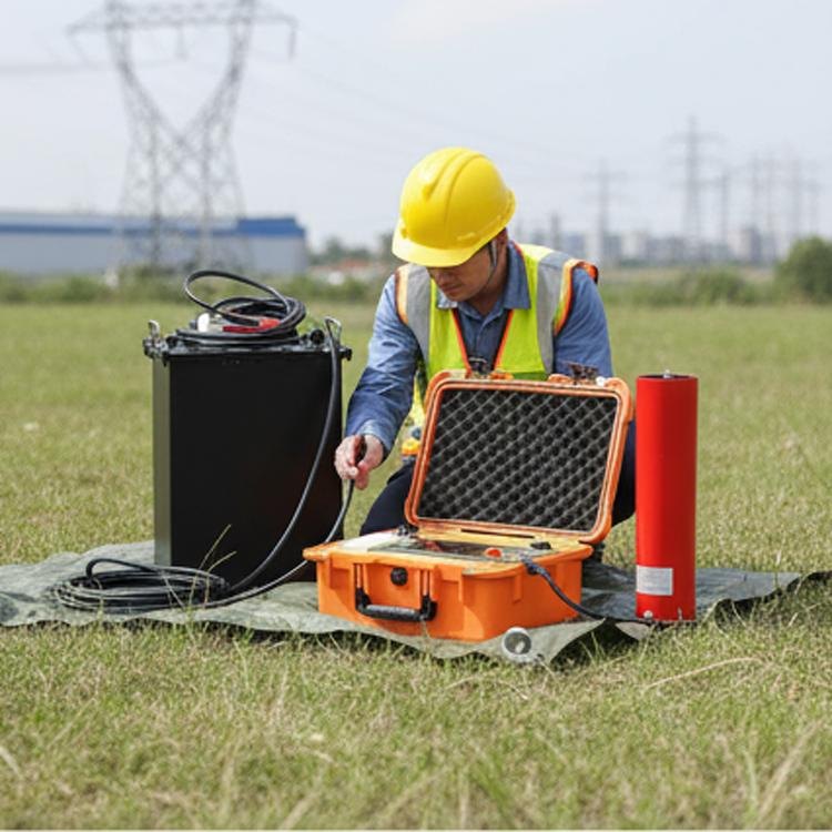
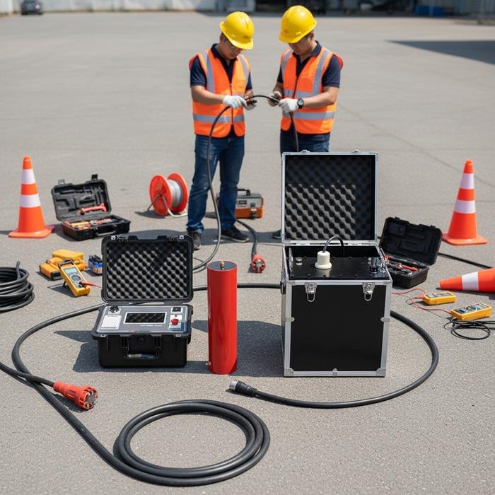
We performed cable fault detection and VLF withstand testing of the 35 kV collection circuits for a grid-connected PV plant (see our Projects page). The photos above were taken on the job. We will publish the complete numeric record — cable model and cross-section, length, measured capacitance, applied test voltage and duration, result and total on-site time — only after we have verified every figure against the original test report. We will not fill this table with rounded or reconstructed numbers.
| Item | Value |
|---|---|
| Industry / location | Grid-connected PV plant, 35 kV collection circuit |
| Cable type & cross-section | Uncertain — pending original test report |
| Cable length | Uncertain — pending original test report |
| Measured capacitance | Uncertain — pending original test report |
| Applied voltage & duration | Uncertain — pending original test report |
| Result (pass / breakdown / retest) | Uncertain — pending original test report |
| Total on-site time | Uncertain — pending original test report |
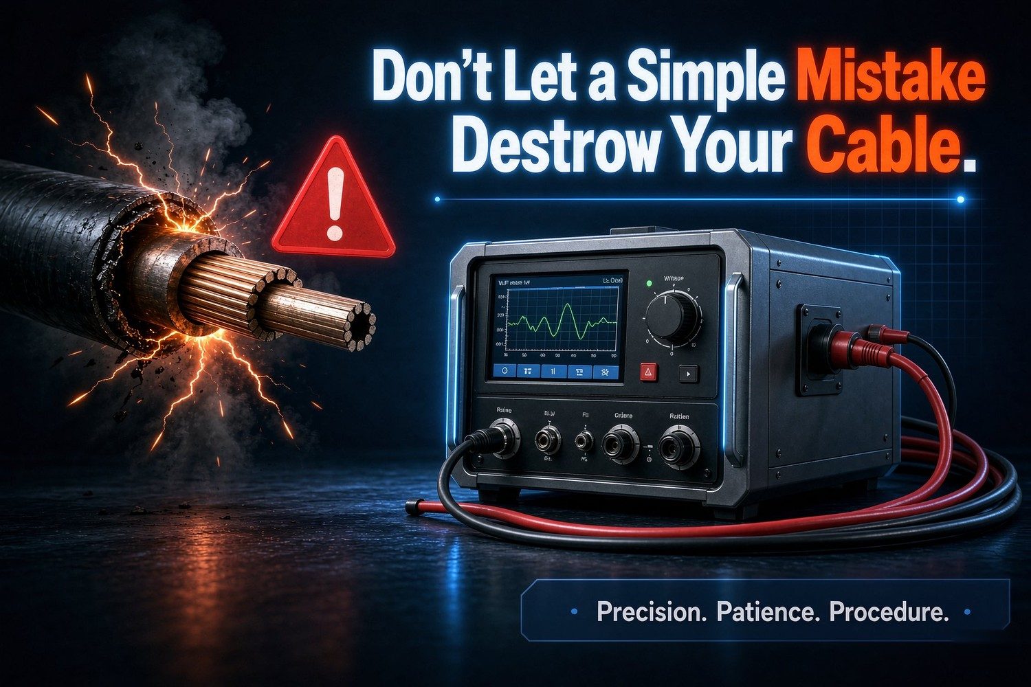
VLF testing seems simple, but poor execution leads to inaccurate data—or worse, cable breakdown. These five hard-earned lessons must not be ignored:
Strict adherence to procedures is non-negotiable.
Short cable, no output. A test object below 0.05 µF capacitance will not output a proper waveform — every one of our sets ships with a 0.05 µF compensation capacitor for exactly this case; connect it in parallel and the waveform comes back. (Documented in our manual, and the red capacitor in the photos above is it.)
Long cable eats the capacity budget. At 0.1 Hz the load limit is only 0.5 µF. Don't order a bigger booster — drop the frequency: 0.05 Hz takes 1.1 µF, 0.02 Hz takes 2.2 µF, 0.01 Hz takes 5.5 µF. Run I = 2πfCU with your cable length first, then pick the frequency.
Unstable site generator. If the output looks wrong on site, check the power source first: our manual requires a portable generator of more than 3 kW, stable 50 Hz, 220 V ± 5%. Undersized gensets are the most common cause of unexplained trips.
Testing a different voltage class or cable length? Send us U0, cross-section and length — our engineers will size the set and confirm the settings.
Ask an engineer — reply within 24 hTell us your cable voltage class, length and test standard — we will propose the right model and quote within 24 hours.
Send Inquiry