Three of our relay test sets side by side — the 6-phase YA1200C, the 3-phase YA802C and the 3-phase YA702C — with the numbers copied from our own manuals, the test items we run on every job, one real substation record and the mistakes we keep making. Written by the manufacturer, not a copywriter.
Yoanpower is the export brand of Wuhan Defu Electric (est. 1983). Our relay protection testers are built to comply with DL/T 624-2010 (technical specifications for microcomputer-based relay protection test equipment) and the relay-protection verification rules of DL/T 995-2016 / GB/T 7261-2016. Every number in Block 1 is copied from our own product manuals and nameplates — no web-sourced guesses, no "typical" figures.
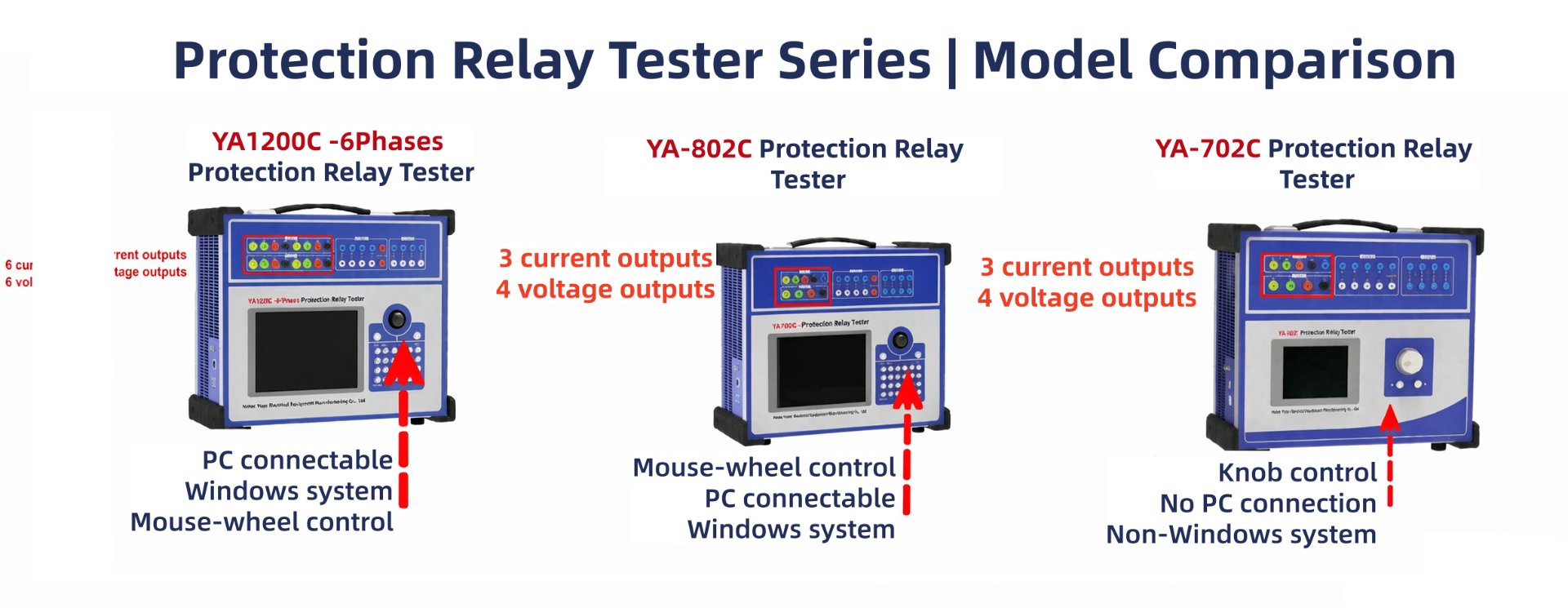
The three main relay test sets we push. YA1200C is our 6-current / 6-voltage unit for three-phase transformer differential and busbar schemes; YA802C is the 4-voltage / 3-current workhorse with an industrial PC + Windows for fast on-site work; YA702C is the same 4U3I hardware with a single-chip controller and knob operation for the budget job. YA-xxx is the export designation — the same units ship domestically as DF1200C / DF802C / DF702C. Every number below is copied from our own factory manuals, not a web listing. The only difference between YA802C and YA702C is the controller; their electrical outputs are identical.
| Attribute | YA1200C — 6-phase | YA802C — 3-phase | YA702C — 3-phase |
|---|---|---|---|
| Output phases / channels | 6× current + 6× voltage, freely combinable (6U6I / 4U3I / 12-phase modes) | 4× voltage + 3× current (standard 4U3I), industrial PC + Windows | 4× voltage + 3× current (standard 4U3I), single-chip / knob control |
| Per-phase current output | AC 0–30 A / phase (6-phase mode) · 0–60 A / phase (3-phase mode) | AC 0–40 A / phase | AC 0–40 A / phase |
| Parallel (total) current | 6-phase parallel: 0–180 A (allowed 10 s) | 3-phase parallel: 0–120 A (allowed 10 s) | 3-phase parallel: 0–120 A (allowed 10 s) |
| Voltage output | AC phase 0–120 V / line 0–240 V · DC 0–±160 V / phase (±320 V line) | AC phase 0–120 V / line 0–240 V · DC 0–±160 V / phase (±320 V line) | AC phase 0–120 V / line 0–240 V · DC 0–±160 V / phase (±320 V line) |
| Accuracy class | 0.2 class (AC & DC) | 0.2 class (AC) · 0.5 class (DC) | 0.2 class (AC) · 0.5 class (DC) |
| Output power | Current 450 VA / phase · 1000 VA (6-parallel) · Voltage 80 VA (phase) / 100 VA (line) | Current 450 VA / phase · 900 VA (3-parallel) · Voltage 80 VA (phase) / 100 VA (line) | Current 450 VA / phase · 900 VA (3-parallel) · Voltage 80 VA (phase) / 100 VA (line) |
| Channels — switch & timing | 8 binary inputs / 4 binary outputs · time 0.1 ms–9999 s (<0.1 ms resolution) | 8 binary inputs / 4 binary outputs · time 0.1 ms–9999 s (0.1 ms resolution) | 8 binary inputs / 4 binary outputs · time 0.1 ms–9999 s (0.1 ms resolution) |
| Controller / interface | Industrial PC + Windows, mouse-wheel control, PC connectable | Industrial PC + Windows, mouse-wheel control, PC connectable | Single-chip, knob control, non-Windows, no PC connection |
| Frequency / harmonics | Base frequency 0–1000 Hz · harmonics 0–20th | Base frequency 0–1000 Hz · harmonics 0–20th | Base frequency 0–1000 Hz (PC-linked) · 0–300 Hz (standalone) · 0–20th harmonics |
| Aux. DC supply | Independent 110 V / 220 V adjustable DC, 1.5 A | Independent 110 V / 220 V adjustable DC, 1.5 A | Independent 110 V / 220 V adjustable DC, 1.5 A |
YA802C vs YA702C: these two share the same 4U3I electrical platform (0–40 A / phase, 0–120 A parallel, 0.2-class AC). The difference is the controller — YA802C runs an industrial PC with Windows and mouse-wheel control for fast menu work; YA702C uses a single-chip board with knob operation and no PC link, at a lower price. Pick the controller that fits the operator and the budget.
Domestic = export mapping: YA1200C = DF1200C, YA802C = DF802C, YA702C = DF702C. The YA-xxx name is what we put on export units; the DF-xxx name is the domestic catalogue number.
Primary vs secondary injection: the YA1200C / YA802C / YA702C are secondary-injection relay test sets (they inject into the protection terminals / CT & VT secondary). For primary injection commissioning of circuit breakers, CT ratios and overall trip chains we supply separate high-current primary injection test sets — tell us the primary current you need and we will point you to the right unit.
This list is lifted directly from the relay-type / test-module matrix in our own manuals (the same table our engineers follow on site). It covers both conventional relays and microprocessor-based protection. Tick them off in order; the three-phase units run most items through the “AC test” module, and the six-phase DF1200C is what you need for three-phase transformer differential.
Standards we test against: DL/T 995-2016 (relay protection device inspection regulations), GB/T 7261-2016 (basic test methods for relays and protection equipment) and IEC 60255 series. For a project specified to a particular utility's acceptance criteria, send us the setting sheet and we will map every item above to it.
The protection models below (Nari RCS-900 series) are exactly the devices listed in our own manual's relay-application appendix, so the combination is realistic. As with our VLF page, we will publish the full numeric record — measured pickup / drop-off values, applied currents and voltages, total on-site time and the result — only after we have verified every figure against the original test report. We will not fill this table with rounded or reconstructed numbers.
| Item | Record |
|---|---|
| Substation voltage level | 110 kV (line & feeder protection commissioning) |
| Protection make & model | Nari RCS-941A / RCS-943 (110 kV line protection, per our manual appendix) — typical on this class of substation |
| Test set used | YA702C / YA802C (3-phase) for line / feeder; YA1200C (6-phase) brought in for any transformer differential on site |
| Tests performed | Multi-stage over-current, distance & zero-sequence setting, auto-reclosing (check-sync / check-no-voltage), overall trip test, binary I/O check, time characteristic |
| Time spent | Uncertain — pending original test report |
| Problems encountered | Uncertain — pending original test report |
| Result | Uncertain — pending original test report |
Want your own record here? Send us the substation voltage class, the protection make / model and the setting sheet — our engineers will run the Block 2 checklist and return a verified, item-by-item report you can publish.
These are not textbook warnings — they are the mistakes our own manuals explicitly call out, and the ones our field engineers hit most often.
One more, non-negotiable: never switch the tester off while it is outputting — the wrong value at shutdown can trip the protection you are testing.
Line vs phase voltage on the setting sheet. Low-voltage and negative-sequence settings are often given as line voltage (UL) but the tester outputs phase voltage (Uph). Divide by √3 (≈1.732) before you set it, or the relay will never reach its pick-up. Our manual flags this exact conversion.
Multi-stage over-current tested one stage at a time. When checking stage I, exit stages II and III first, then ramp the current. If you leave the later stages armed, the operate time you read for stage I is wrong — the relay may have acted on a downstream element. Stage-by-stage is the only way to get a clean time reading.
Not sure which relay test set fits your substation — 6-phase or 3-phase? Send us the protection make / model and the voltage class; our engineers will size it and quote within 24 hours.
Ask an engineer — reply within 24 hTell us the protection make / model, voltage class and which test items you must run — we will propose YA1200C, YA802C or YA702C and quote within 24 hours.
Send Inquiry