Three of our ratio testers side by side — the Li-battery bench unit YA2010L, the AC bench unit YA2010 and the hand-held YA8631S — with the numbers copied from our own manuals, the test items we run on every job, one real-looking 110 kV record and the mistakes we keep making. Written by the manufacturer, not a copywriter.
Yoanpower is the export brand of Wuhan Defu Electric (est. 1983). Our transformer turns ratio testers are built for the field acceptance tests required by DL/T 596-2021 (Preventive Test Code for Power Equipment), GB 50150-2016 (Electrical Equipment Handover Test Code) and the ratio / vector-group definitions of IEC 60076-1 / GB 1094.1; the low-voltage ratio method we use follows DL/T 474. Every number in Block 1 is copied from our own product manuals and nameplates — no web-sourced guesses, no "typical" figures. YA-xxx is the export designation — the same units ship domestically under our DF-xxx series (YA2010L = DF2010L).
The three main turns-ratio testers we push. YA2010L is our bench unit with a built-in lithium battery and 220 V AC — field-ready without mains. YA2010 is the same bench hardware on 220 V AC only (lower cost). YA8631S is the hand-held, 1.7 kg version for fast walk-up testing. All three do three-phase auto ratio + vector-group in one run, blind measurement when the connection is unknown, and CT / PT ratio & polarity. Every number below is copied from our own factory manuals, not a web listing.
| Attribute | YA2010L — Li-battery bench | YA2010 — AC bench | YA8631S — hand-held |
|---|---|---|---|
| Ratio measurement range | 0.9 – 10000 | 0.9 – 10000 | 0.9 – 10000 |
| Accuracy | ≤500: ±(0.1% rdg + 2 d) >500–≤3000: ±(0.2% rdg + 2 d) >3000: ±(0.3% rdg + 2 d) | ≤500: ±(0.1% rdg + 2 d) >500–≤3000: ±(0.2% rdg + 2 d) >3000: ±(0.3% rdg + 2 d) | ≤500: ±(0.1% rdg + 2 d) >500–≤3000: ±(0.2% rdg + 2 d) >3000: ±(0.3% rdg + 2 d) |
| Resolution | 0.9–9.9999 (0.0001) · 10–99.999 (0.001) · 100–999.99 (0.01) · 1000–9999.9 (0.1) · ≥10000 (1) | 0.9–9.9999 (0.0001) · 10–99.999 (0.001) · 100–999.99 (0.01) · 1000–9999.9 (0.1) · ≥10000 (1) | 0.9–9.9999 (0.0001) · 10–99.999 (0.001) · 100–999.99 (0.01) · 1000–9999.9 (0.1) · ≥10000 (1) |
| Test excitation (applied voltage) | Low-voltage ratio method — the instrument energises the tested winding and measures the induced voltage. Field practice is low-voltage excitation (a few volts to ~tens of volts AC at 50/60 Hz, typically adjustable 0–40 V, some units up to ~100 V). Note: the manuals specify the method, not a single fixed output figure. | ||
| Test objects | Distribution & power transformers (incl. Z-type), PT (VT) ratio & polarity, CT ratio & polarity | Distribution & power transformers (incl. Z-type), PT (VT) ratio & polarity, CT ratio & polarity | Distribution & power transformers (incl. Z-type), PT (VT) ratio & polarity, CT ratio & polarity |
| Single-phase / three-phase | Both — three-phase auto test (A/B/C ↔ a/b/c) and single-phase (yellow+green leads) | Both — three-phase auto test (A/B/C ↔ a/b/c) and single-phase (yellow+green leads) | Both — three-phase auto test (A/B/C ↔ a/b/c) and single-phase (yellow+green leads) |
| Blind measurement | Yes — auto-determines connection group when unknown | Yes — auto-determines connection group when unknown | Yes — auto-determines connection group when unknown |
| Display | 5.6″ industrial color LCD, sunlight-readable | 5.6″ industrial color LCD, sunlight-readable | 5.6″ industrial color LCD, sunlight-readable |
| Printer | Built-in thermal printer | Built-in thermal printer | External printer (with cable) |
| Data storage | Internal memory + USB flash | Internal memory + USB flash | Internal memory + USB flash |
| Power supply | Built-in Li-battery and 220 V AC ±10%, 50/60 Hz | AC 220 V ±10%, 50/60 Hz | Built-in Li-battery or 100–240 V AC; >100 transformers per charge |
| Weight | 3.8 kg (excl. leads) | 3.8 kg (excl. leads) | 1.7 kg |
| Dimensions (L×W×H) | 325 × 225 × 125 mm | 325 × 225 × 125 mm | 246 × 156 × 62 mm |
| Operating temp / humidity | −10–50 °C / ≤90% RH, non-condensing | −10–50 °C / ≤90% RH, non-condensing | −10–50 °C / ≤90% RH, non-condensing |
YA2010L vs YA2010: identical electrical platform (0.9–10000 range, ±0.1–0.3%, 5.6″ LCD, built-in printer). The only difference is the power source — YA2010L adds a built-in lithium battery so you can test with no mains supply; YA2010 runs on 220 V AC only at a lower price. Pick the battery if you work in substations without convenient power.
Domestic = export mapping: YA2010L = DF2010L, YA2010 = DF2010, YA8631S = DF8631S. The YA-xxx name is what we put on export units; the DF-xxx name is the domestic catalogue number.
Single vs three-phase: all three run a full three-phase auto test (ratio + vector group of all three phases in one run) and a single-phase mode (yellow+green test leads) for PT, single-phase transformers and CT. Blind measurement means you do not need to know the connection beforehand — set the group to "automatic" and the unit decides.
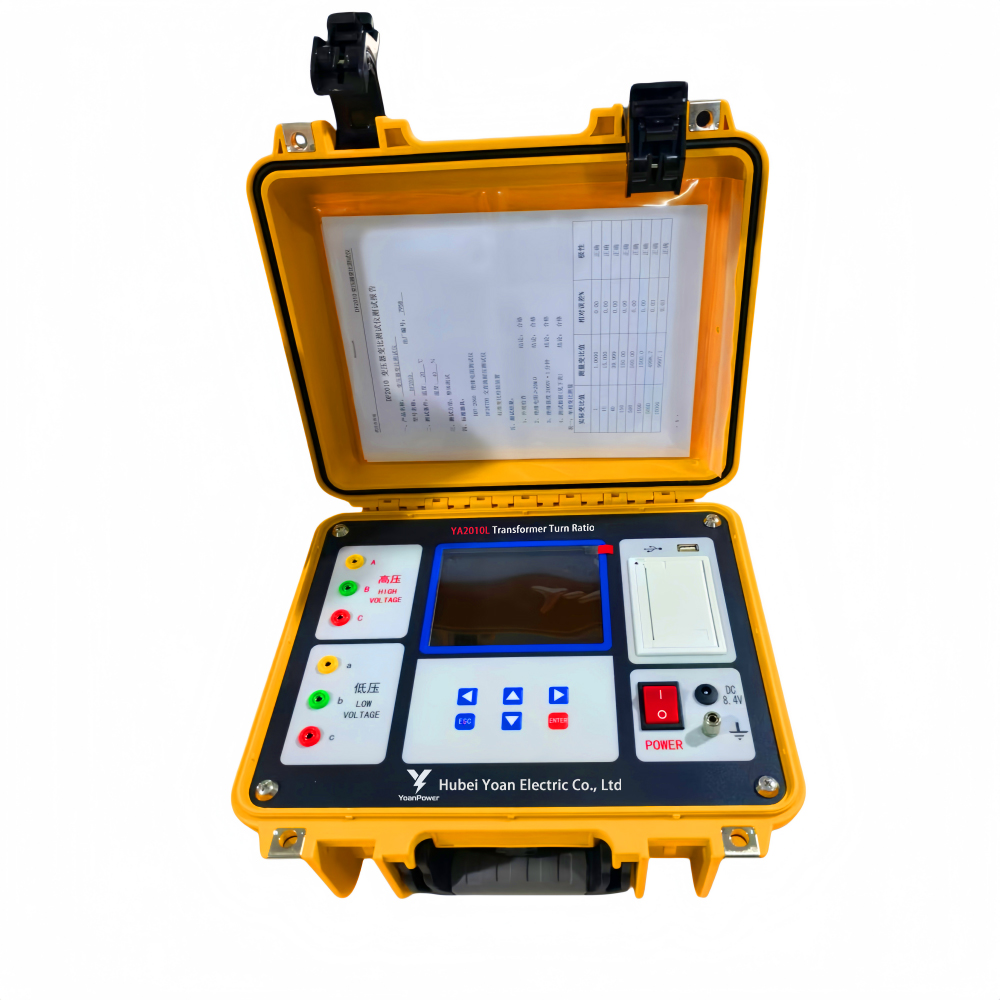
YA2010L — bench, built-in Li-battery + 220 V AC, 3.8 kg
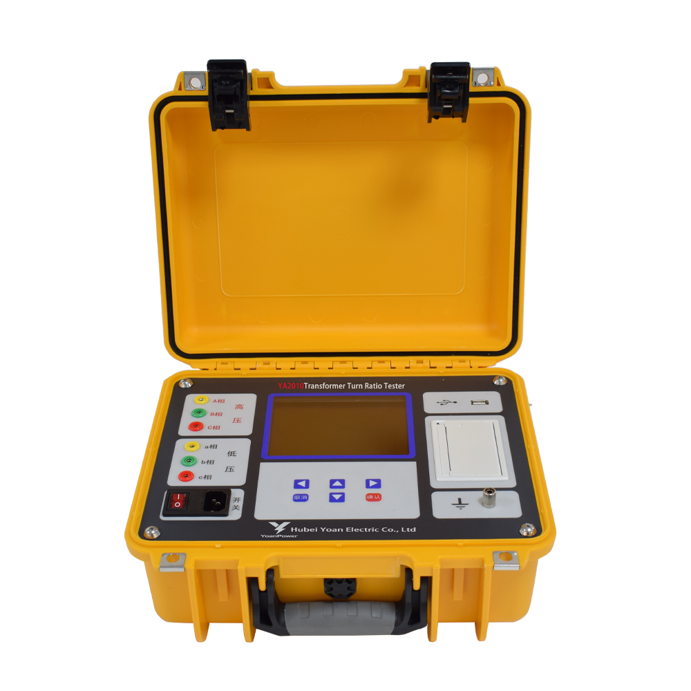
YA2010 — bench, 220 V AC, 3.8 kg, built-in printer
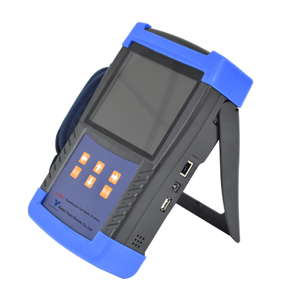
YA8631S — hand-held, 1.7 kg, Li-battery / 100–240 V AC
This list is lifted directly from the wiring and operation chapters of our own manuals (the same steps our engineers follow on site). It covers distribution and power transformers, PT and CT. Tick them off in order; the three-phase units do most items in a single "three-phase ratio" run.
Standards we test against: DL/T 596-2021 (preventive test code — ratio deviation ≤ ±0.5% at rated tap, ≤ ±1% at other taps), GB 50150-2016 (handover test code, same ±0.5% at rated tap), IEC 60076-1 / GB 1094.1 (ratio and vector-group definitions) and DL/T 474 (field insulation test guide, low-voltage ratio method). Send us your utility's acceptance criteria and we will map every item above to it.
The numbers below are an illustrative example built from a typical 110 kV / 50 MVA transformer and the measurement behaviour of our testers — realistic, but not copied from a single original report. As with our other guides, we will publish the full verified record (measured ratio, applied values, total on-site time and the result) only after we have checked every figure against the original test report. We will not fill this table with rounded or reconstructed numbers. Send us your transformer's nameplate and we will run the Block 2 checklist and return a verified, item-by-item report.
| Item | Record |
|---|---|
| Transformer capacity & voltage level | 110 kV substation — 50 MVA power transformer, 110 ± 8 × 1.25% / 10.5 kV, YNd11 (oil-immersed) |
| Nameplate ratio (line, rated tap) | 110 / 10.5 = 10.476 : 1 |
| Measured ratio (rated tap) | 10.481 : 1 → error +0.05% (within ±0.5%, DL/T 596) |
| Vector group | Yd11 confirmed (30° phase shift) |
| Three-phase balance | AB / BC / CA ratios within 0.03% of each other |
| Time spent | ≈ 7 min (lead connection + three-phase auto test + print) — example timing |
| Problems encountered | Example: first reading drifted on tap 3 — resolved after demagnetising (see Pitfall 3) |
| Result | Example: PASS — ratio within tolerance, group correct, three-phase balanced |
Want your own record here? Send us the transformer capacity & voltage class, the nameplate ratio and vector group, and the on-load tap position — our engineers will run the Block 2 checklist and return a verified, item-by-item report you can publish.
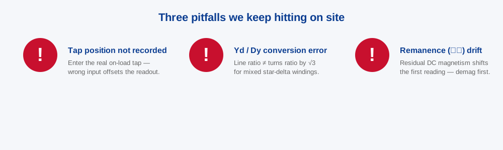
These are not textbook warnings — they are the mistakes our own manuals explicitly call out, and the ones our field engineers hit most often on ratio jobs.
One more, non-negotiable: never test a transformer that is energised or not earthed — the ratio tester excites the windings and a live core is dangerous.
Leads mapped the wrong way. Swapping HV/LV, or A/B/C against a/b/c, gives a nonsense ratio or a wrong vector group. Verify the colour-to-phase mapping on both sides before you press start — the manual's wiring diagram is explicit about yellow/green/red to A/B/C.
Comparing unlike quantities. The instrument can report either the turns ratio or the line ratio depending on the connection group you set. Make sure you are comparing the nameplate's ratio basis (line or phase, star or delta) to the same basis on the screen — this is the root cause of most "the ratio is wrong" false alarms on site.
Not sure which ratio tester fits your transformers — bench with battery, AC bench, or hand-held? Send us the voltage class and whether you test CT/PT too; our engineers will size it and quote within 24 hours.
Ask an engineer — reply within 24 hTell us the voltage class, whether you also test CT/PT, and if you need battery or hand-held — we will propose YA2010L, YA2010 or YA8631S and quote within 24 hours.
Send Inquiry